| < Previous page | Next page > |
Two Hinged Plane's Design
This is a common design procedure used by Multiplane users. Ezigrade allows you to select a common intersecting line as a hinge line. Ezigrade forces the design to intersect along this common line.
Please be aware that every additional constraint imposed upon a surface leads to additional volumes of dirt needed to be moved. Also be aware that if you wish two planes to match you can also specify additional smoothing which smooth's the area between the surfaces to get a smooth match.
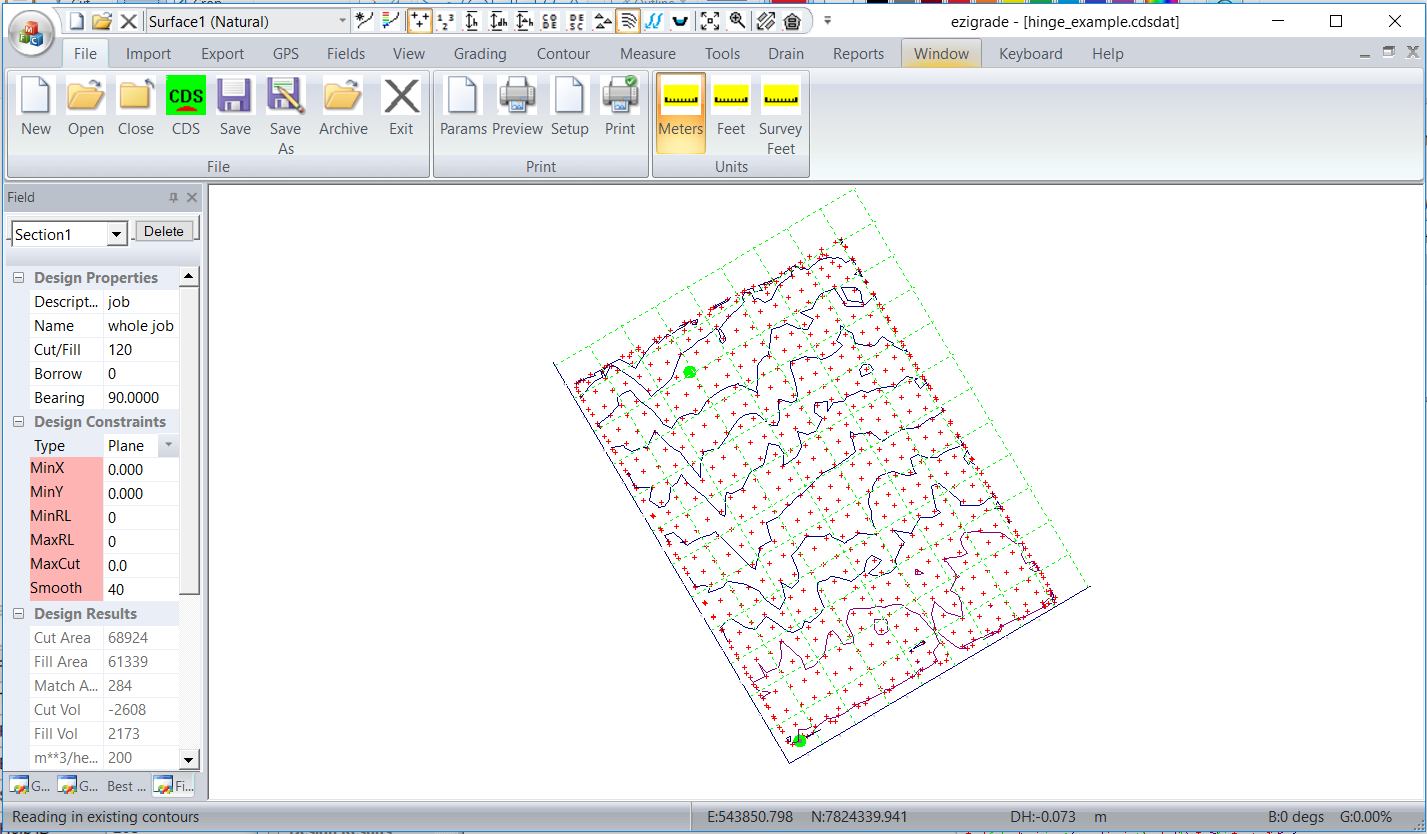
Open Ezigrade , and then from the File - Open menu open up the "hinge_example.cdsdat" example. The natural surface will be displayed. We have already set the position of the grid. You can modify it by left clicking on it and moving and rotating using the grip points. In this example the water runs from the top of the job towards the bottom.
In this example we intend to have two sections that are vertically orientated with the hinge link between the two. We need to first draw in some section lines.
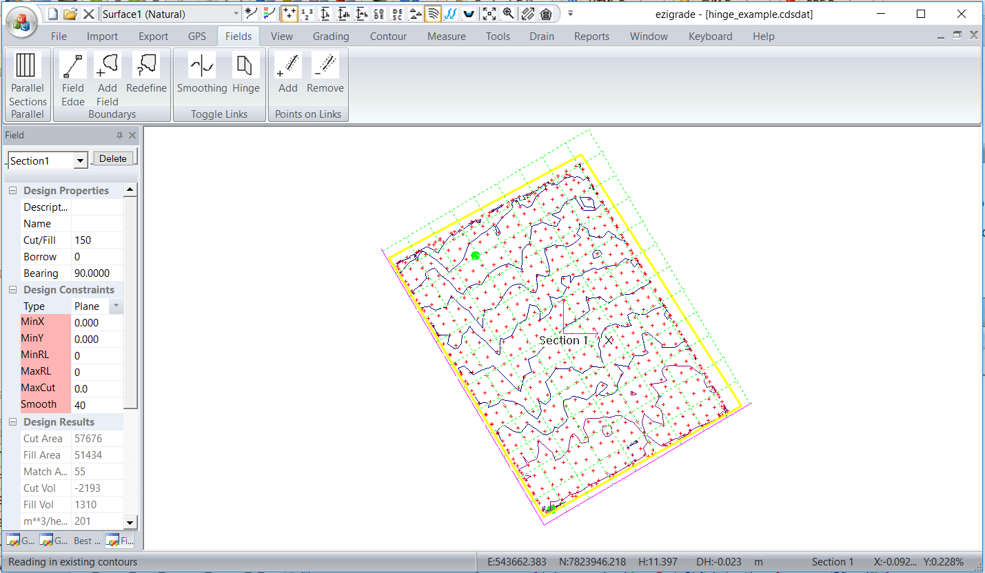
From the "Fields" menu click on the Fields -> Insert Field Edge. Draw a closed surface that encloses the whole job. Ezigrade will close the section if you finish by finishing on the start point. You need to hit the "Enter" key to finish the process. You should have something similar to that shown below:
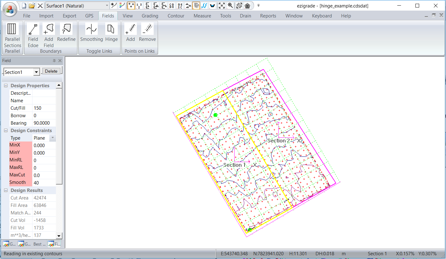
We intend to split this into two with a vertical line. Again from the Fields menu ->Insert Field Edges and draw in a line starting at the top to the bottom. Again finish the process by hitting the "Enter" key. Ezigrade will ask whether you wish to create two new sections. Answer yes. We have the following:
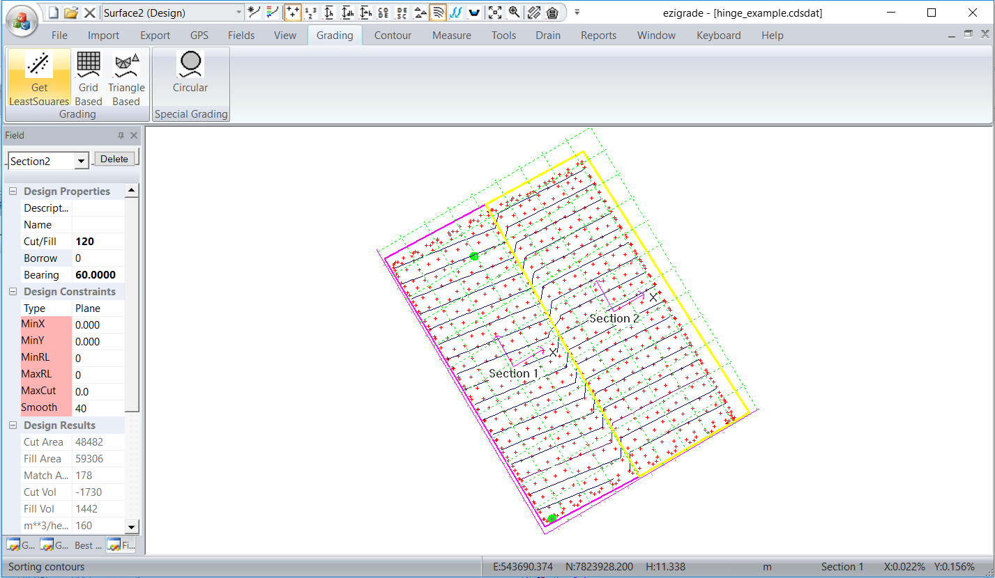
If we now perform grading -> triangle based we get the following. It is fairly ugly around the join. There is a transition across the join. In this example there are triangles straddling the join. This is leading to the issue.
We do have an option of smoothing across the join. If we click on the smoothing and do again we can get something like this.
This may or may not be acceptable but is an easy way of getting things to match. However in this case we only have a laser and need the sections to match exactly.
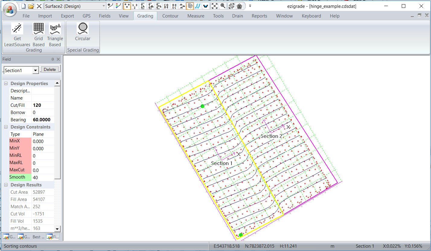
In this case we need to define the middle link as a hinge link. Left click on it to select; and then from the Fields -> Toggle Hinge Links sets it as a hinge. If you have a link defined as a hinge you can turn it off using the same procedure. If we rerun the grading we get the following:
If you look closely you will notice that the change of grade doesn't necessarily lie along the hinge link. The change of grade occurs at the triangle edges which meander around the hinge link. In practice you would not notice this in the field.
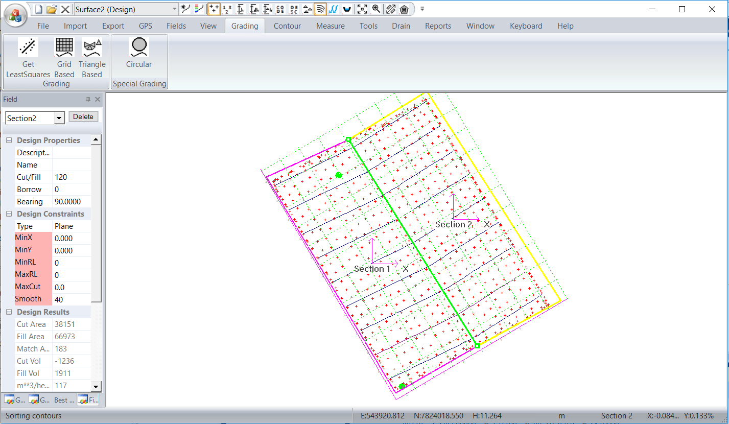
To create an exact solution we need points along the link so that triangles form along the hinge. There is an option to do this. Click on the hinge link so it turns green. How click on the Fields -> Add (points on link). A dialog pops up:
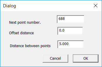
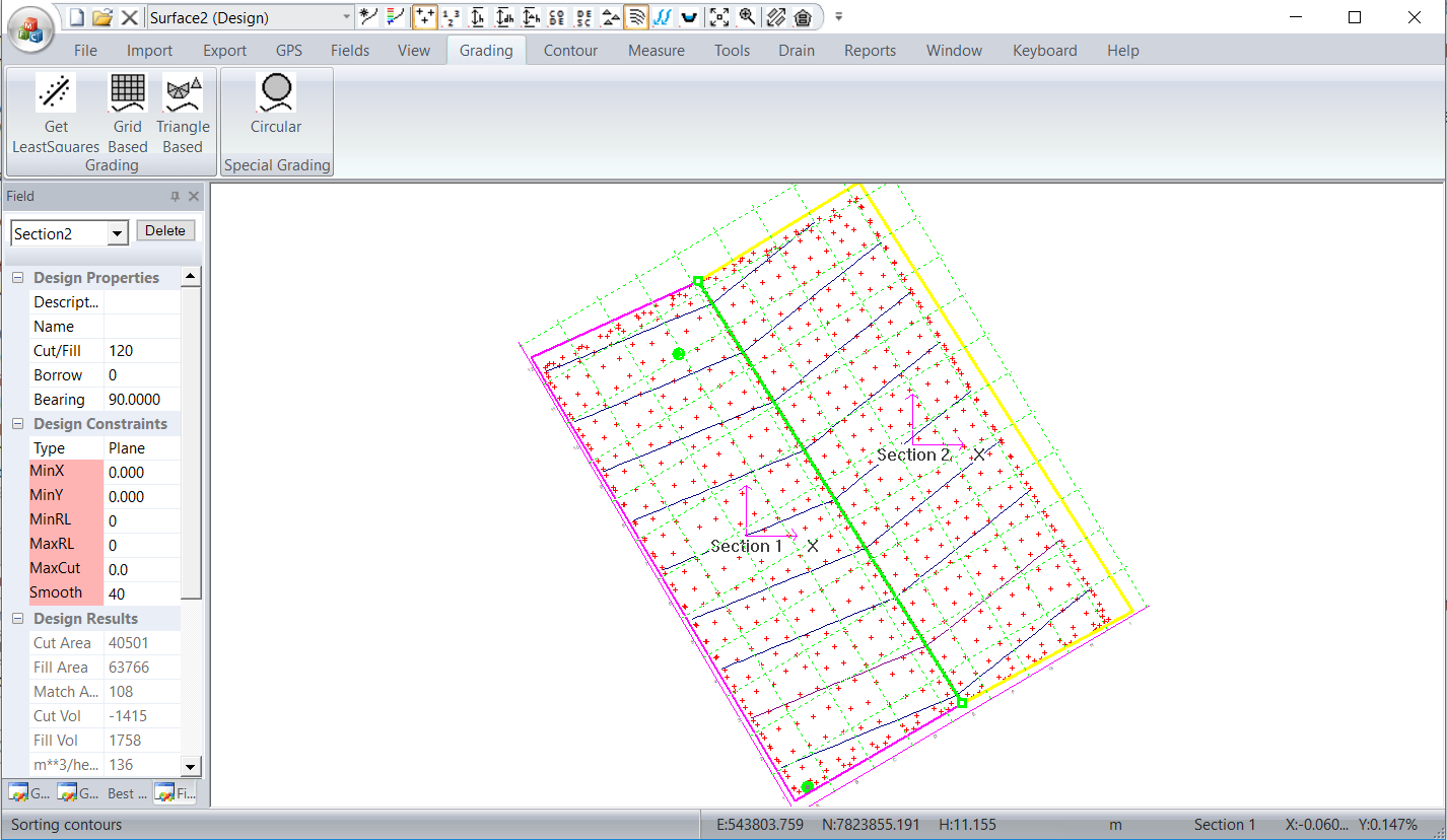
Set the offset distance to 0. This forces points along the hinge link. Ezigrade automatically recreates appropriate triangles etc to include these extra points. If you rerun again you get the following. The change of grade here occurs exactly along the hinge link.
 |