| < Previous page | Next page > |
Convert Civil Design to Field Level II file
This tutorial is slightly more complicated than the previous example. It shows how you can go about importing data from more than one source.
In this tutorial we go through the steps that you would follow to create a Trimble Field Level II Civil Design; given text data that defines the natural surface and the design data in a DWG format.
CDS which is bundled with Ezigrade already gives you this option of creating civil solutions. However if your Civil Designer already has existing software that they are familiar with ; then this is a quick and easy way of levering there existing knowledge. I would also note that CDS can import data in other major formats such as LandXML etc.
In this example we are supplied with two files. A text file that contains our raw data file as well as our proposed design in a dwg. It is possible to create the compatible file using only the final design. However we then lose the ability to display the cut/fill values on our Trimble FMX display.
Features in .gps Control Block
I will run through a basic outline of the data in the control block. This gives us an idea of what we can expect out.
Importing Survey points
If we only have design data then ignore this section.
We have been given a txt file as follows, the data is in feet:
1,0.000000,0.000000,247.770000,MB N33:26:26.789 / W88:34:57.803 0
2,89.000000,-1062.000000,236.370000,BM1
3,55.000000,1584.000000,262.600000,B
4,68.000000,1599.000000,262.900000,B
5,78.000000,1603.000000,262.990000,B
6,93.000000,1606.000000,263.040000,B
7,108.000000,1606.000000,262.940000,B
8,118.000000,1606.000000,262.810000,B
We can import this directly into Ezigrade as a Trimble Data file. Open up Ezigrade. Before importing the data we need to first create a new job. Use the "File" menu and then "New" option. We are going to call this job "mill1".
To import this data use the following steps:
We get the following:
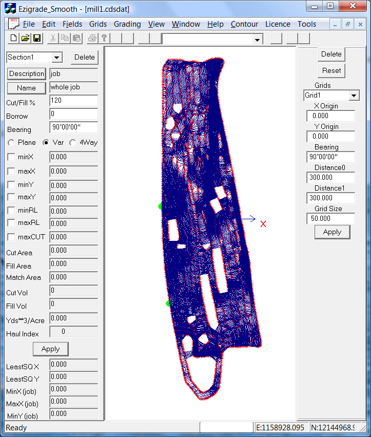
The contours are set for typical agricultural jobs. This land is a bit steeper so it would be good to have fewer contours. You will also notice that there are some missing triangles in the middle of the job. There are a couple of parameters under Contour - Surface parameters that we can tweak to control this.
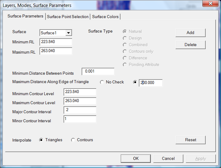
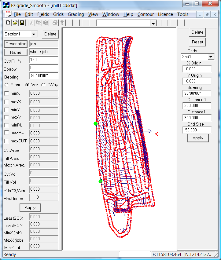
If you click OK and then under Contour - Form Model this will recreate the triangular surface. You can then reform the contours under Contour - Create Contours. We end up with the following. You will note that the bottom of the job is a bit messy. There are some options that you can play with to delete some of the triangles in this area. This area of the job is not overlaid by the design data so I would suggest we leave as it is. You will notice the two green dots. The solid green is the Master Bench while the green with a grey middle is a bench mark point.
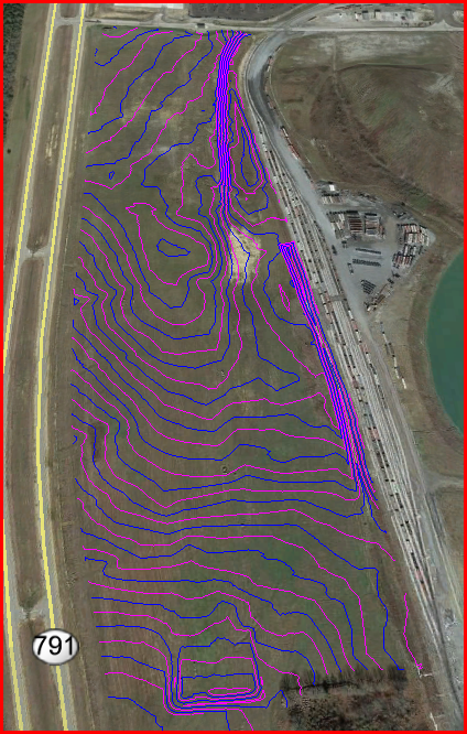
At this stage I suggest we check the spatial position of our data. To do this I suggest we use Google Earth as it is free and available. From the "File" menu click on export "Google Earth". In this example we have exported the Contours.
 Importing the Design
We have been given a design as a DWG file. Before trying to import the DWG we suggest that you first view the file with a cad editor. If you don't have one we suggest the free DraftSight or alternatively Nanocad. In this example the DWG contains the design surface as a series of 3D faces plus a number of strings that define a couple of features as well as the outline of the triangles.
In this example I believe the data is in State Plane Coordinates. However we need to ultimately convert the data to UTM coordinates to be Field Level compatible. This will be fixed up later within CDS. (You could also ask your Civil Designer to setup the data in UTM if necessary)
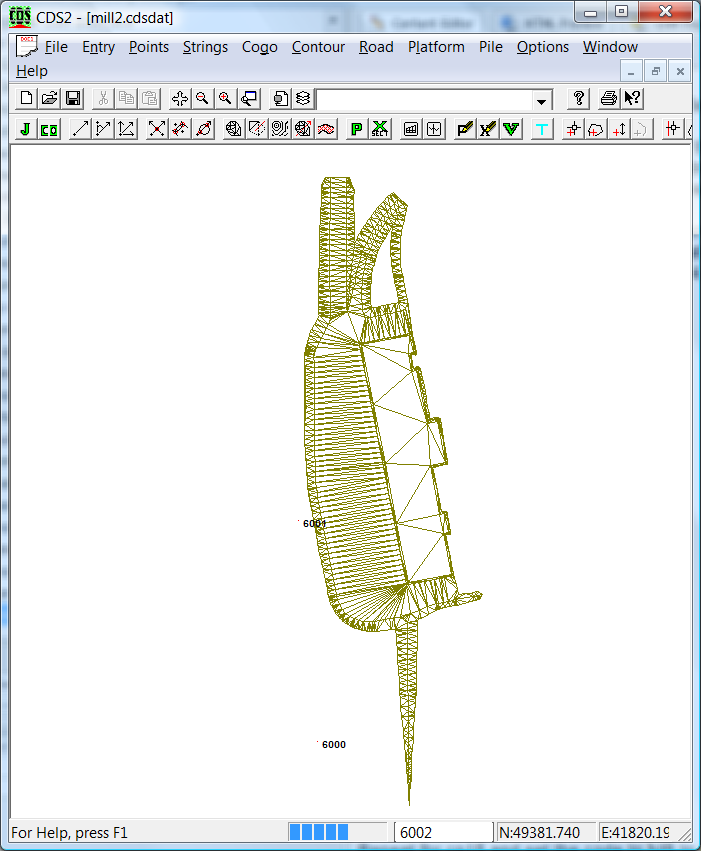
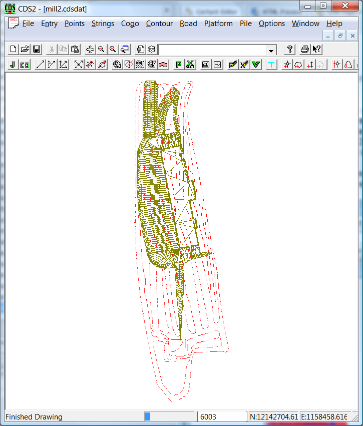
The import DWG option is contained within CDS. Open up CDS and create a new job. We suggest that you keep the natural and design points separate and join them together later. Lets call this job "Mill2". To import go to the "File" - "Import DWG/DXF" option.
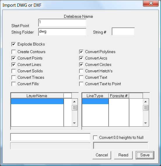
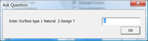
To import you click on "Read" and when ready click on "Save". A warning; As at November 2015 we are not presently supporting the latest version of dwg. If you get an error message resave the DWG as a 2010 version file. We will be fixing this shortly. When importing you will be asked the following. CDS needs to know whether the 3D faces in the DWG are natural or design triangles. In this case we are importing a design so make sure you enter the value "2".
Once read in; if you wish to display the contours. Go to Contours - Surface Parameters and change the surface to surface 2 which is the design surface. After importing a DWG we suggest that you run some of the quality assurance routines. Sometimes DWG files define string as separate sections rather than one contiguous line. Run this from "Options" - "QA Routines" - "Filter Duplicate Coordinates". Untick the "Keep Points Contained In Strings" and tick "Delete Higher Numbered One".
We have been given the following information on two additional points:
cp14 N 48874.46 E 42629.61 Ht 236.45
cp15 N 49935.57 E 42537.76 Ht 247.767
and we wish point cp15 to be the Master Bench at N33:26:26.789 W88:34:57.803.
We need to know the UTM coordinates of the Master Bench point. There are a number of online resources that you can use. One that works is: http://www.latlong.net/lat-long-utm.html This gives UTM coordinates in meters of 352880.74E and 3701272.95N. This example is in feet so we also need to convert these values in meters to feet.
To enter these two reference points click on "Points" - "Add" and then click on the screen. We get the following dialog. I suggest you change the Point Number to something that we can remember. Enter in the appropriate coordinates. Make the code BM1 to tell us it is a bench mark and set the description to cp14.
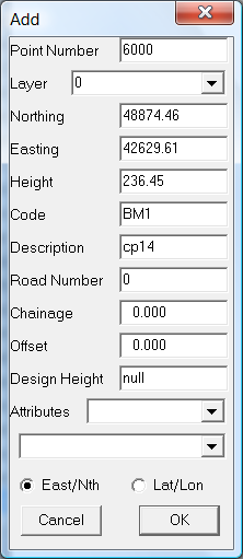
Repeat for cp15 and set the code to MB to indicate it is the master bench. You will see the two entered points relative to the design.
We now need to translate the job to be UTM. To achieve this we enter a point at UTM (feet) coordinates and then translate the existing points so that the BM point 6001 lies over the UTM feet coordinates. Enter a point 6002 in UTM feet (E1157742.894 W12143259.670) as above.
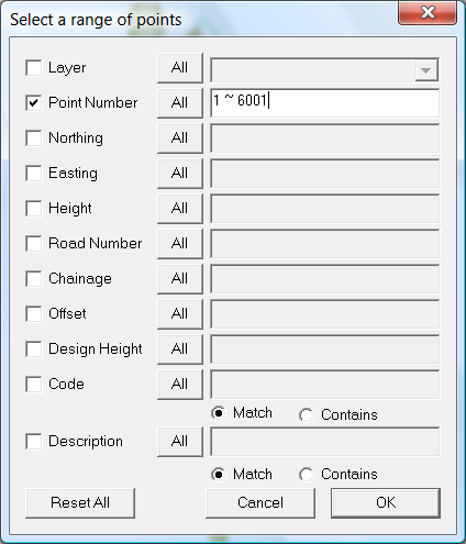
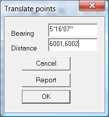
All the visible points will be selected. Alternatively you could select the points by an enclosing polygon. Now we need to do the translation. Click on "Points" - "Translate" and you will get the dialog below. You probably don't know the bearing and distance; but CDS can calculate these for you. Click into the Bearing edit box and type the letter P ; this run's the P command which stands for Point to Point. Type in 6001,6002 and this calculates the bearing. Do the same for the Distance and then click OK.
You should now check the distance between points 6001 and 6002. It should be 0.000
Combining the Natural and Design Jobs
In this example we will copy all the natural points into the design surface we have. Alternatively we could create a new surface and copy both jobs into it.
Before copying points is is best to make sure any of the point numbers in both jobs don't overlap. If they do we need to renumber anyway. It is best to do it first as we have more control. Make sure both jobs are open in CDS and display them side by side. Use the "Window" - "Tile Vertically" option. In these jobs both sets of data start at point 1. To avoid conflict I am going to change the point range of the natural surface points to start at 20000. To do this click into the "Mill1" job and then "Points" - "Select" - "Select All". Now run the "Points" - "Compress Numbering" and set the start point to 20000.
Go back into the Mill1 one job again and select all the points. Now click on the "Copy" icon. Now click into the Mill2 job to give it the focus. Now click on the "Paste" icon. Mill2 now contains both sets of data.
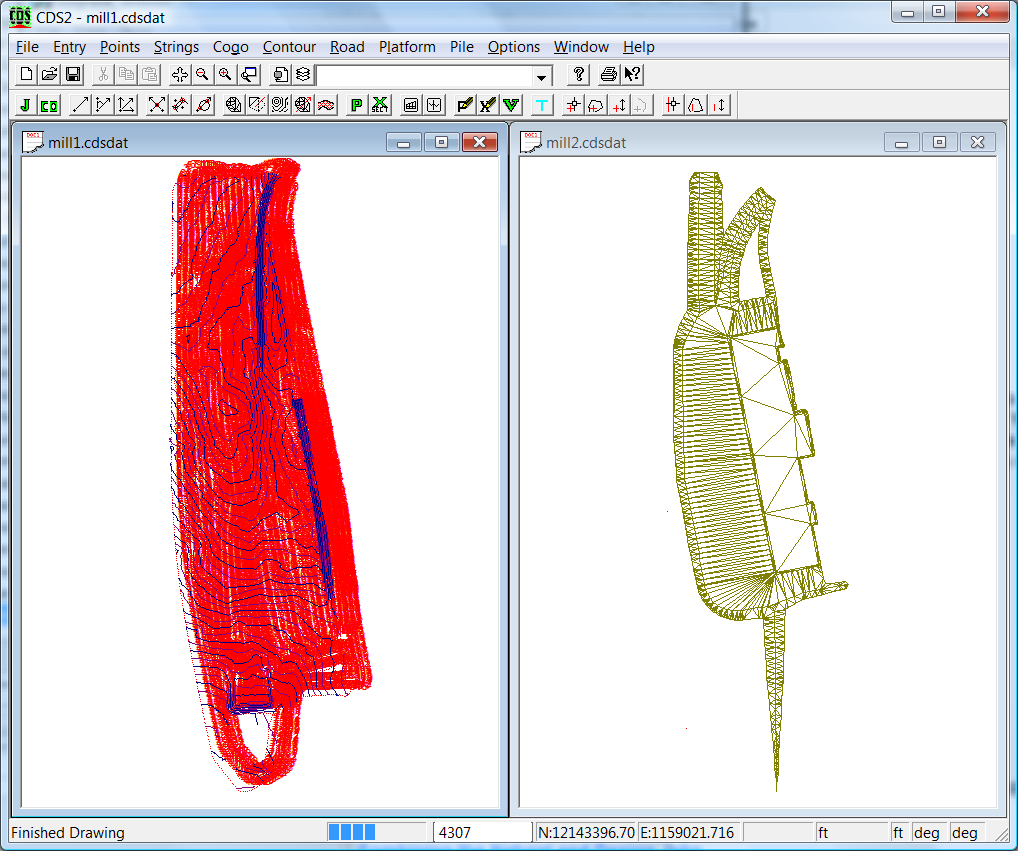
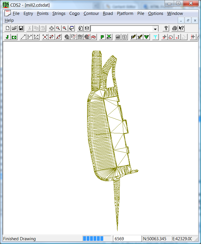
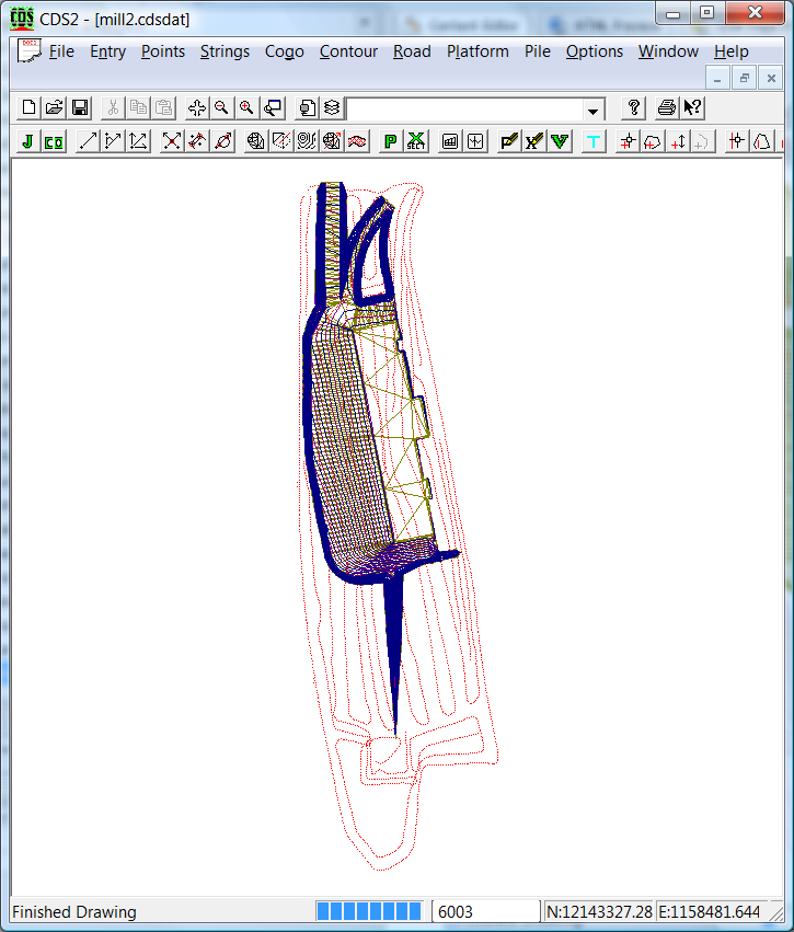
The data should appear something similar to below. We are displaying the design triangles and the natural surface points.
You will need to reform the surface1. From the "Contour" menu click on "Surface Parameters" and hit the reset button. Make sure you go to the "Point Selection" tab and also do a reset. Reform the triangles and display the contours as a check.
 Creating the Trimble Field Level File
We are now in a position to create the .gps file. This needs to be done from Ezigrade. Within CDS go to the "File" - "Close and Reopen in Ezigrade" option. Once in Ezigrade run the "File" - "Export Trimble Machine" option. Set the values as below. In this case we are in UTM Zone 16. You normally set the "Distance Between Points" value as small as possible so that the data still fits. Be careful using the "Field Rotation" option as apparently some of the earlier Field Level consoles don't support field rotations. If you know more we are happy for you to tell us.
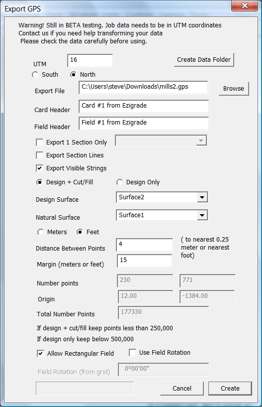
Once happy hit the Create button and it will be done.
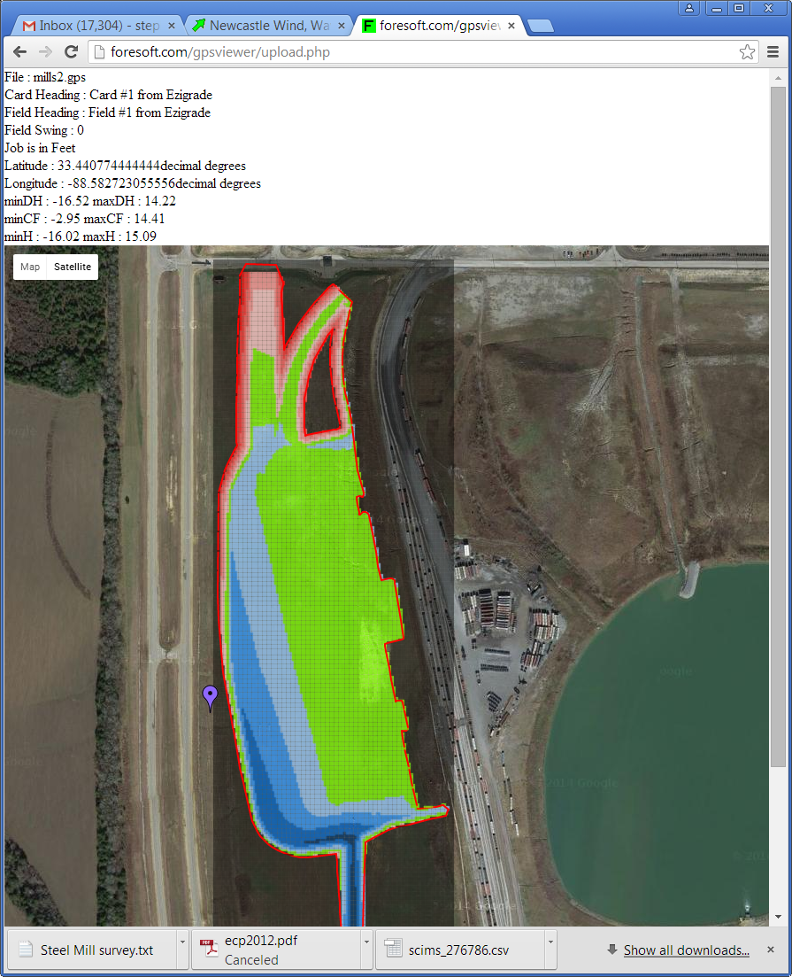
We now suggest that you give it a rough check before sending out to your clients. We have an online checker at:
http://foresoft.com/gpsviewer/browsefile.php
If you run this you can see our design as follows:
 |