| < Previous page | Next page > |
Adding a Drain to a Grading Design
Please note this is preliminary documentation and may change in the future.
We have a surface that is to be graded. There is an existing surface drain running through the existing field. We want to grade the existing surface with a multiple plane type design and then add in a drain that match's the grading design.
Here we design the grading first and leave the area for the drain blank. In this tutorial we will start with the grading design already done. If you need help with this process; then please refer to some of the previous tutorials on how to do this. We are starting with the following natural surface. You can see the drainage easement that we have ignored for the initial design.
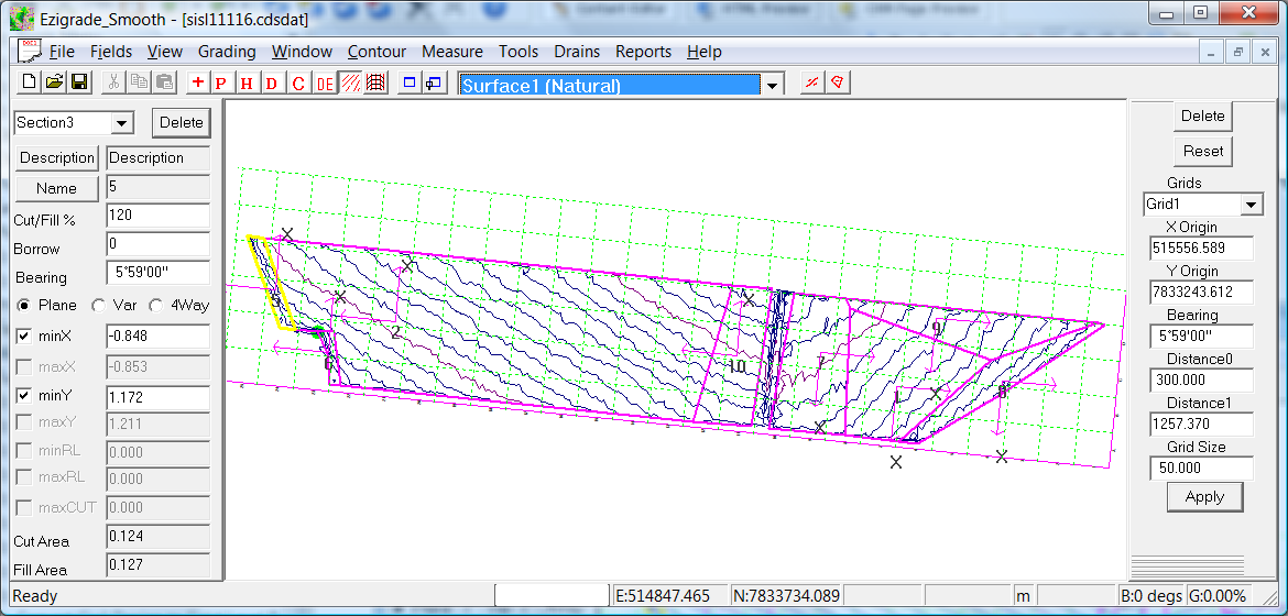
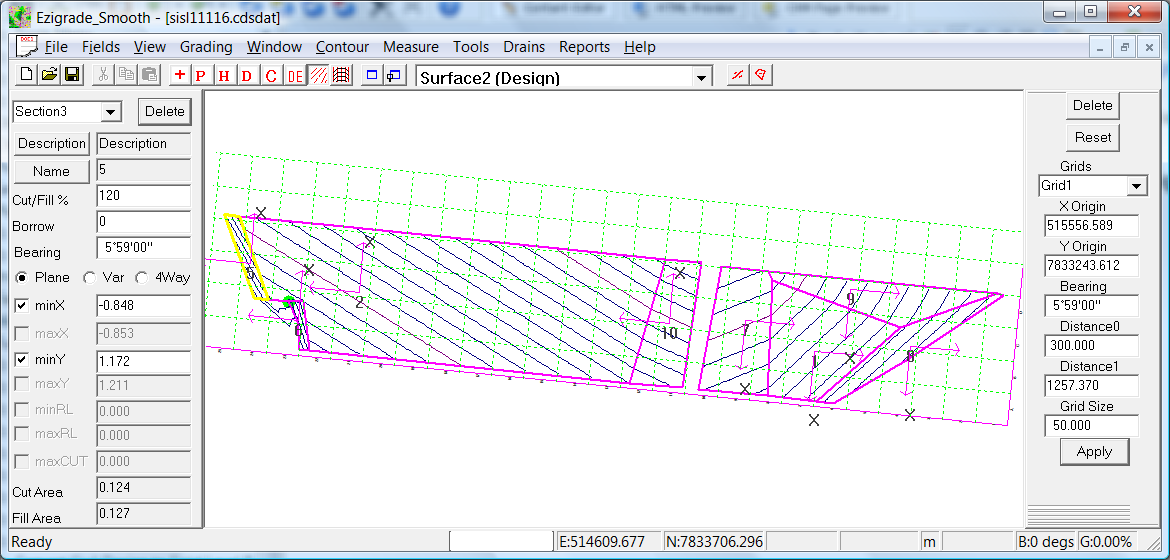
Our initial design ignoring the drain gives us the following:
 Our tutorial starts now.
The first thing is to design the profile of the drain. You will notice that the grades along the right edge of the drain are slightly different to the grades along the left. To match we are going to need to run the profile from the top left of the easement to the bottom right of the easement. It doesn't matter if we don't get it right first time. We can vary the plan view, profile and batter grades to get a match.
Click on the Drain - Insert Drain profile menu item. Left click on the screen for start position and move the cursor to the bottom of the easement and click again. You will see the next part of the line if we continue to move the mouse. Here we are defining a straight drain so now click on the "Enter" key to finish. We have the following:
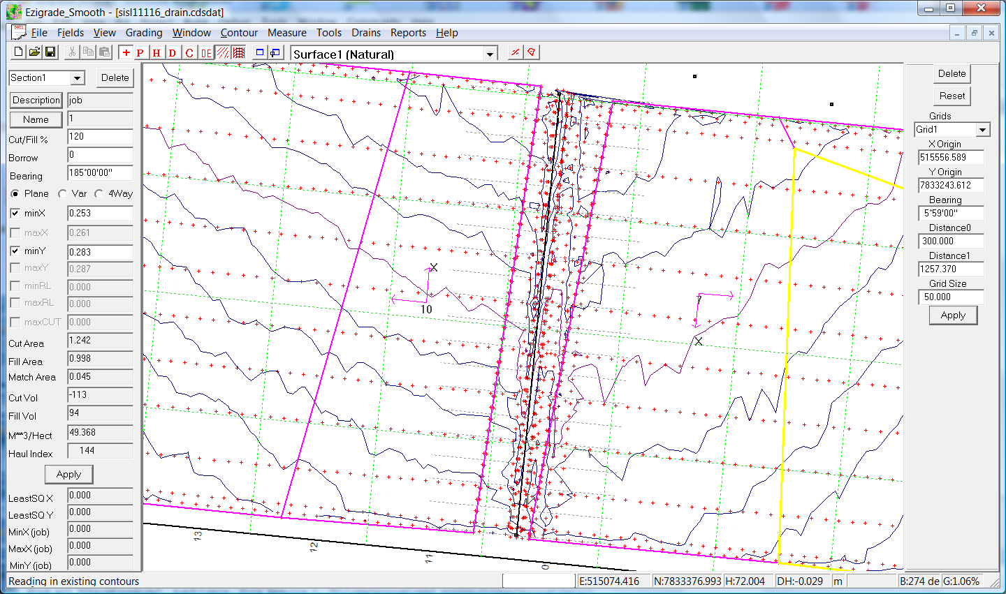
You can see the drain center line of our drain shown in black. We now wish to design the profile. Click on the Drains -> Design Profile. A new view is shown. Click on the "Add" button and click in a point at the start and the end. Hit the "escape" key to end add mode. If you wish to move a point, click on the move button and then left click on a design node and keep the left mouse button pressed; move the mouse. To delete a node, click on "Delete" and then click on the node to be deleted.
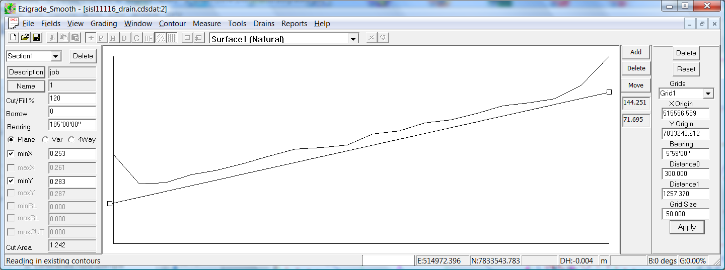
Normally you would have set start and end points for the drain. In this case I am going to match the top of the drain with the existing graded solution. In this example we have four parameters we can vary:
There may also be other engineering constraints such as the amount of water the drain needs to be able to move. Maximum batter slopes if we are doing pivot or linear irrigation, or which to be able to drive through the drain at a certain speed.
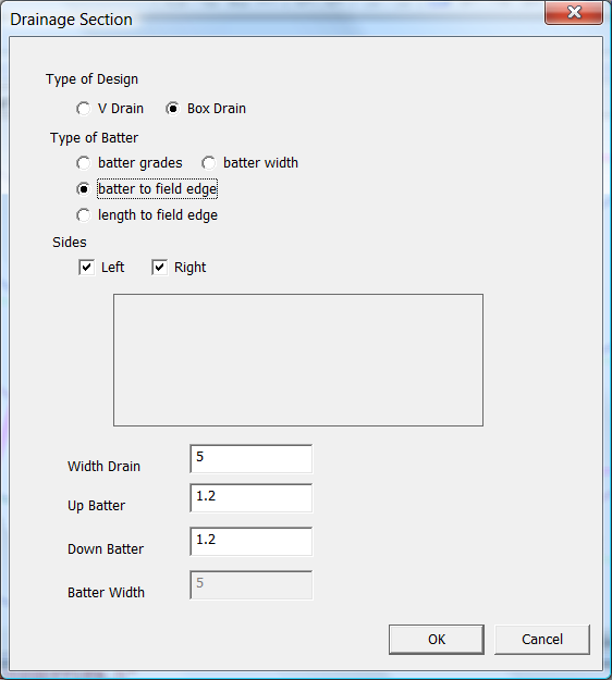
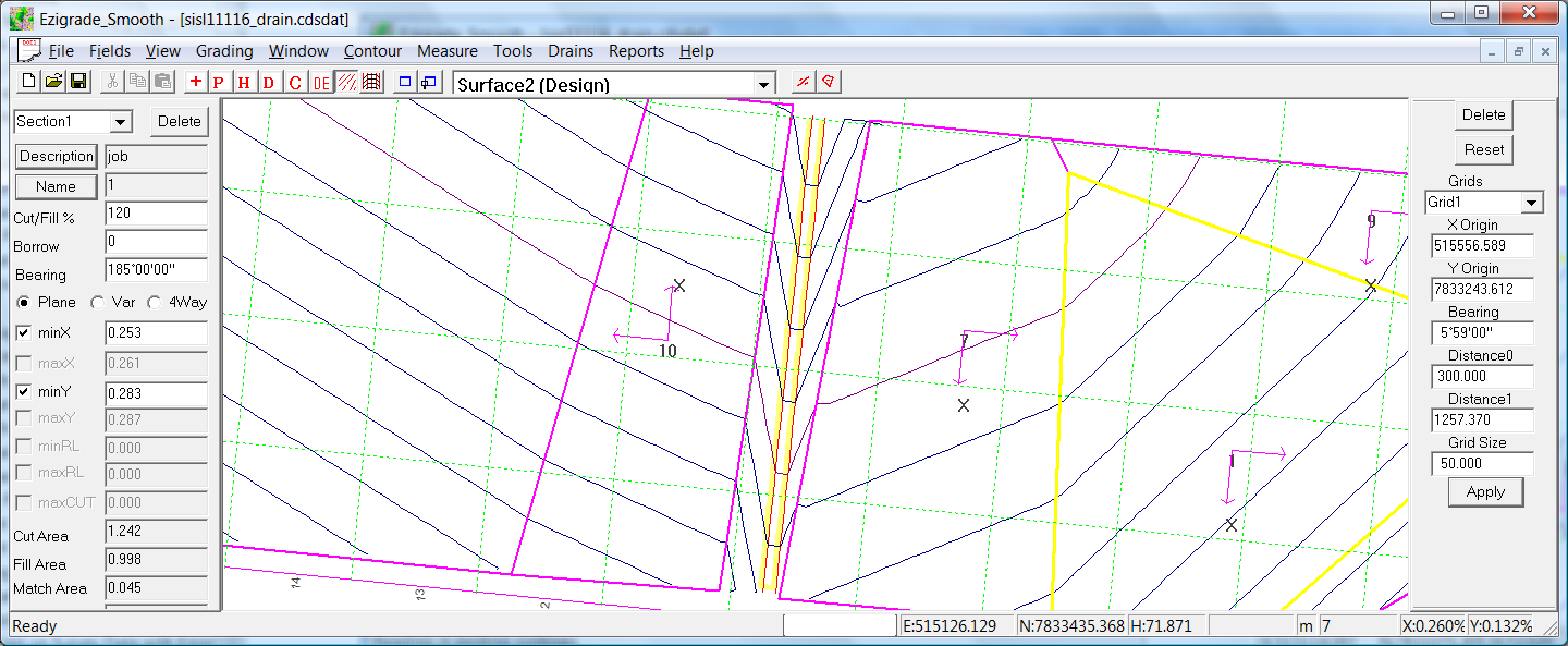
The next step is to specify the section parameters. Click on the Drains -> Design Section menu item.
We are going to use a drain width of 5 meters and batter slopes of 1.2% and see how we go.
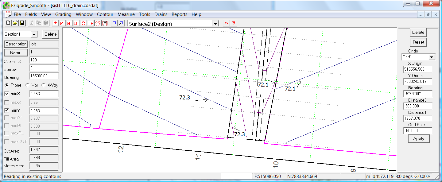
Click OK to finish with the dialog. Now click on the Drains -> Recalculate menu item to redo and display our drainage design. We get the following. Looking at the screen we can see that on the left our initial design is ending underneath our graded surface. On the right we are ending up above the graded surface. We can achieve a match by moving the whole drain to the right. However this means that the drain capacity would be reduced and in heavy rain; the water may flow over the graded section. However in this design this is acceptable. Alternatively we could have changed the respect grades on left and right to match.
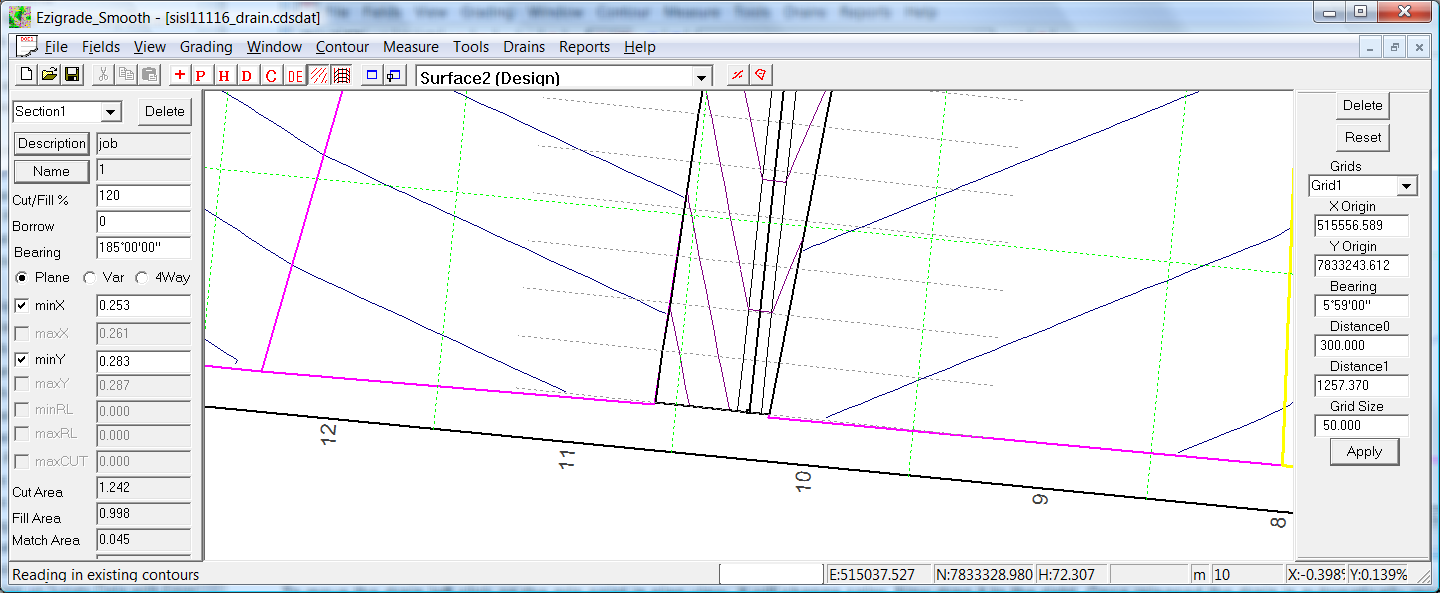
To move the drain left click on the grip point in plan view. It will change color. Now drag it to the right. Once released the drain is automatically recalculated. Iterate the process until you are happy with the result. In this case it is closer. However we are now a bit high on both sides. To correct for this we can go back into the profile design and drop the design slightly. Repeat the process at the top of the screen to match the start of the drain. As the graded surface is linear and the drain is linear; if we match at the start and the end; then we will get a match in the middle as well.
After playing with these parameters we get a match; as below.
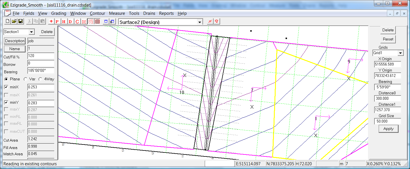
We are now happy with the design. The next stage is to create a finished design surface. Click on the "Drains -> Merge Drain into Design" option. As a user you don't need to know this but: Ezigrade puts in extra points into the database along the edge of the bottom of the drain as well as the daylight points. Any existing points within the drainage corridor are made non-contourable and breaklines are added along the drain so that the triangles form correctly. Unclick the "Show Drains" icon so that we can view the base surface underneath. If for any reason you are not happy with the result; then simply click the "Drains -> Unmerge Drain Design" and the design surface is reset to what it was.
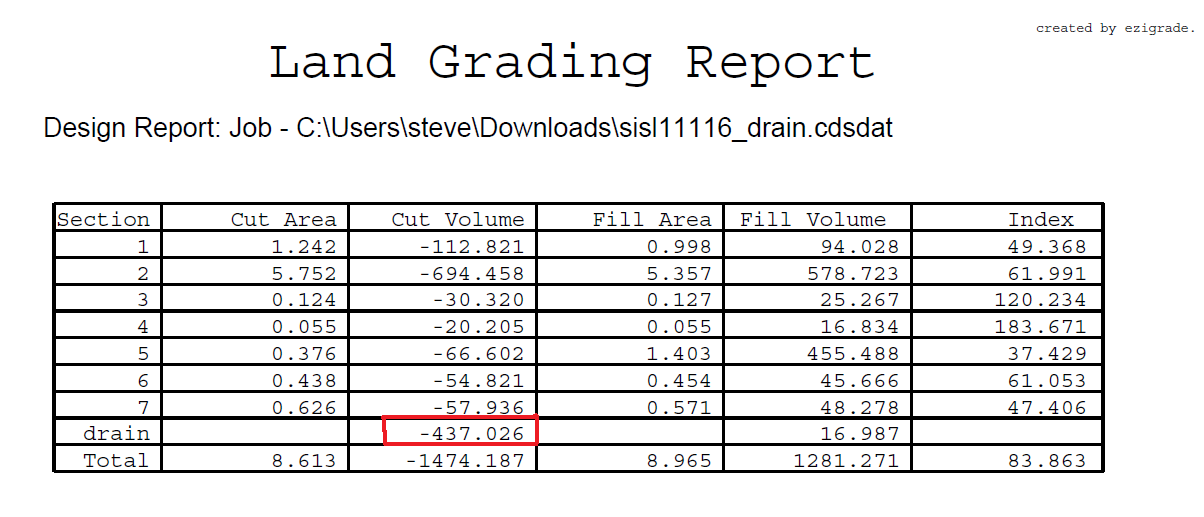
The next step is to create a report that includes the drainage etc. Use the "Reports -> PDF Combined Report". It includes the volume of dirt that needs to be removed or if a bank to be filled. It is worth checking that the total volumes balance. If not you can add borrow to some of the fields when grading and iterate the process.
 |