| < Previous page | Next page > |
Pipes Menu
Please note that we have only just implemented this functionality. If you have a job you wish to design then please do not hesitate to send us any data and we can work through the design for you.
At present we are concentrating on the plan and profile design. We haven't yet looked at the hydraulic equations to calculate the actual pipe sizes to use.
If you have any constructive comments on extra functionality or bug reports then please let us know. If you don't tell us we don't know.
Often referred to in the States as Tile Drainage.
These menu items allow one to design a subterranium drainage system. Subsoil water is drained via a series of pipes that ultimately exist the area. The pipe hierarchy consists of laterals, submains and mains all joined together. At present Ezigrade allows you to design the pipe topology, both in plan view and in profile for individual pipes. Once designed you can export aan excel CSV file for price calculations. You can also export ESRI shape files and or Trimble fieldlevel.xml files so that you can enact the design in the field.
At present we don't include any software to size the pipes that are designed.
Please remember that Ezigrade also includes routines for surface ditch design as well as surface land-levelling. This allows one to design a field that uses a combination of both tile drainage and existing surface drainage to get the best of both worlds.
Insert Main:
This allows you to click in the plan view alignment. You firstly move to the exit point of the pipe and left click. Move the mouse and left click again. Keep adding in alignment points while you work your way from the outlet to where the pipe starts. Enter any Main pipes first.
Insert SubMain:
This allows you to click in the plan view alignment. You firstly move to the exit point of the pipe and left click. This could be on an existing Main pipe that has been previously entered. Ezigrade will automatically snap onto an existing Main pipe. Move the mouse and left click again. Keep adding in alignment points while you work your way from the outlet to where the pipe starts.
I
nsert Lateral:
This allows you to click in the plan view alignment. You firstly move to the exit point of the pipe and left click. This could be on an existing Main pipe or a SubMain pipe that has been previously entered. Ezigrade will automatically snap onto an existing Main or SubMain pipe if applicable. Move the mouse and left click again. Keep adding in alignment points while you work your way from the outlet to where the pipe starts. You could also be running the Lateral from an existing surface drain.
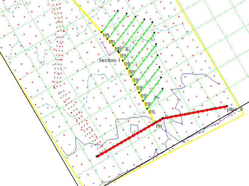
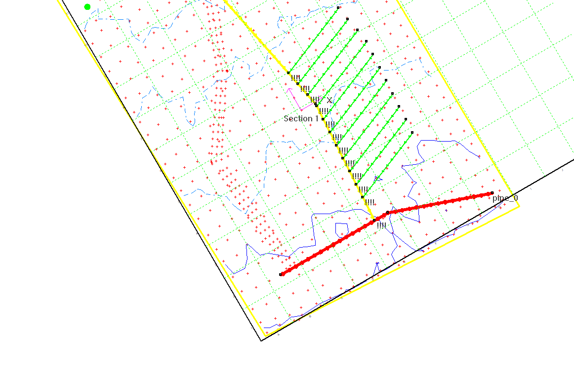
After running these three commands we could end up with the following. The main pipe is shown red, the submain is shown yellow and the lateral is shown in green.
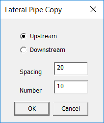
 Copy (Laterals)
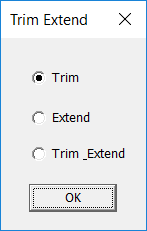
 Trim
This allows us to trim the edge and / or extend the Lateral pipes. Click on the Trim command and you are prompted to draw a trim line as shown below.
Select
This allows you to select more than a single pipe. You are prompted to draw an intersecting line. Every pipe that intersects this line is selected.
After a pipe is selected you can delete the pipe, set constraints etc. Hitting escape clears the selection.
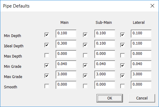
Defaults
This lets you set appropriate defaults for the main, submain and lateral pipes. The values are remembered between jobs.. The following dialog is shown:
 Set Selected Constraints
This sets the appropriate constraints from the above dialog for any selected pipes.
Set All Constraints
This sets all pipe constraints.
Profile
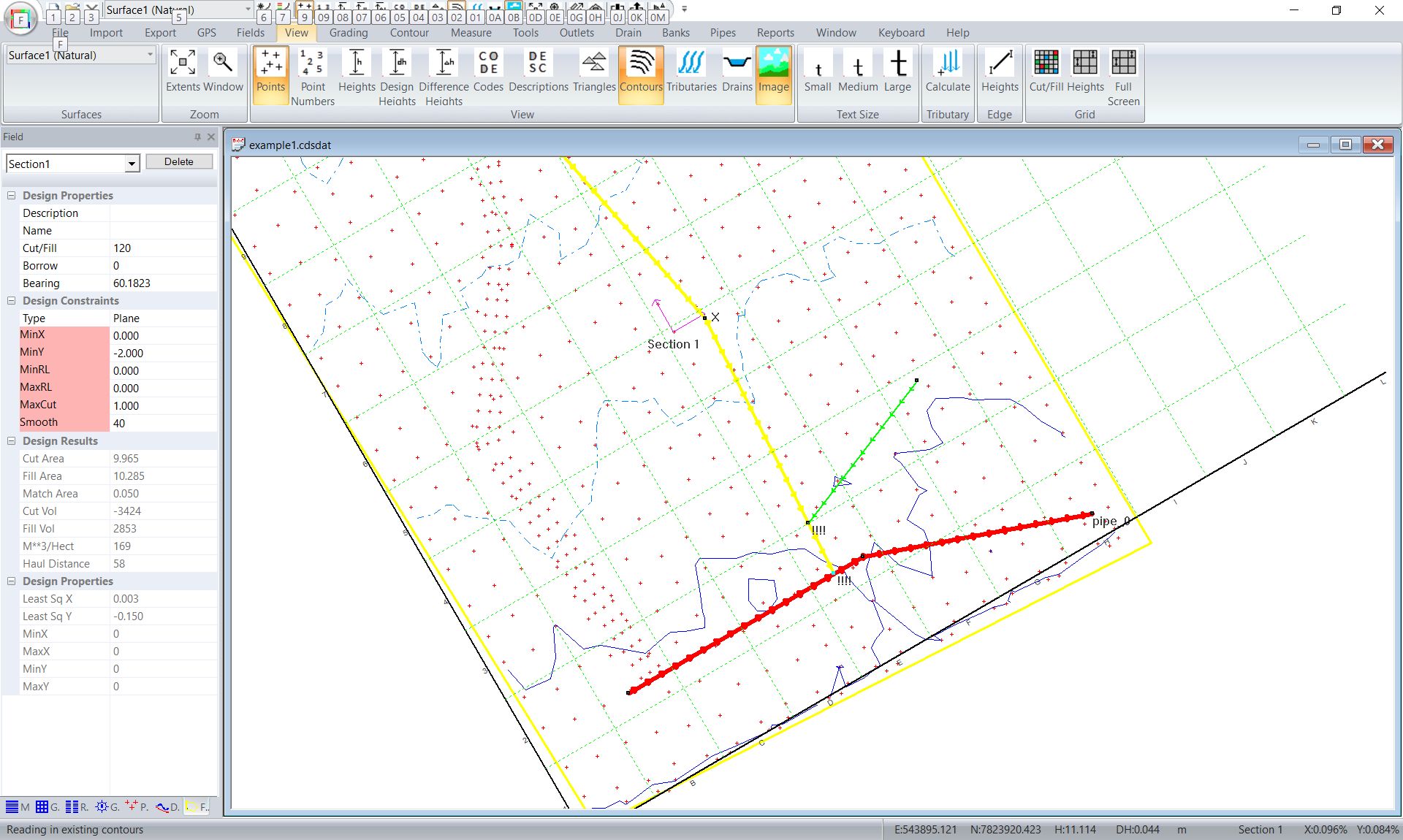
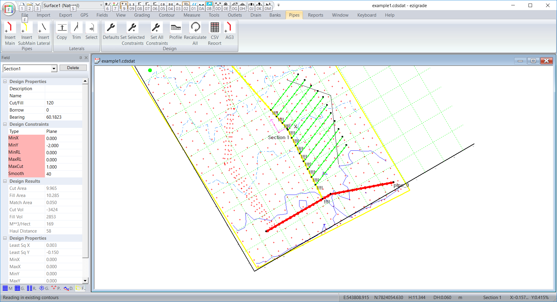
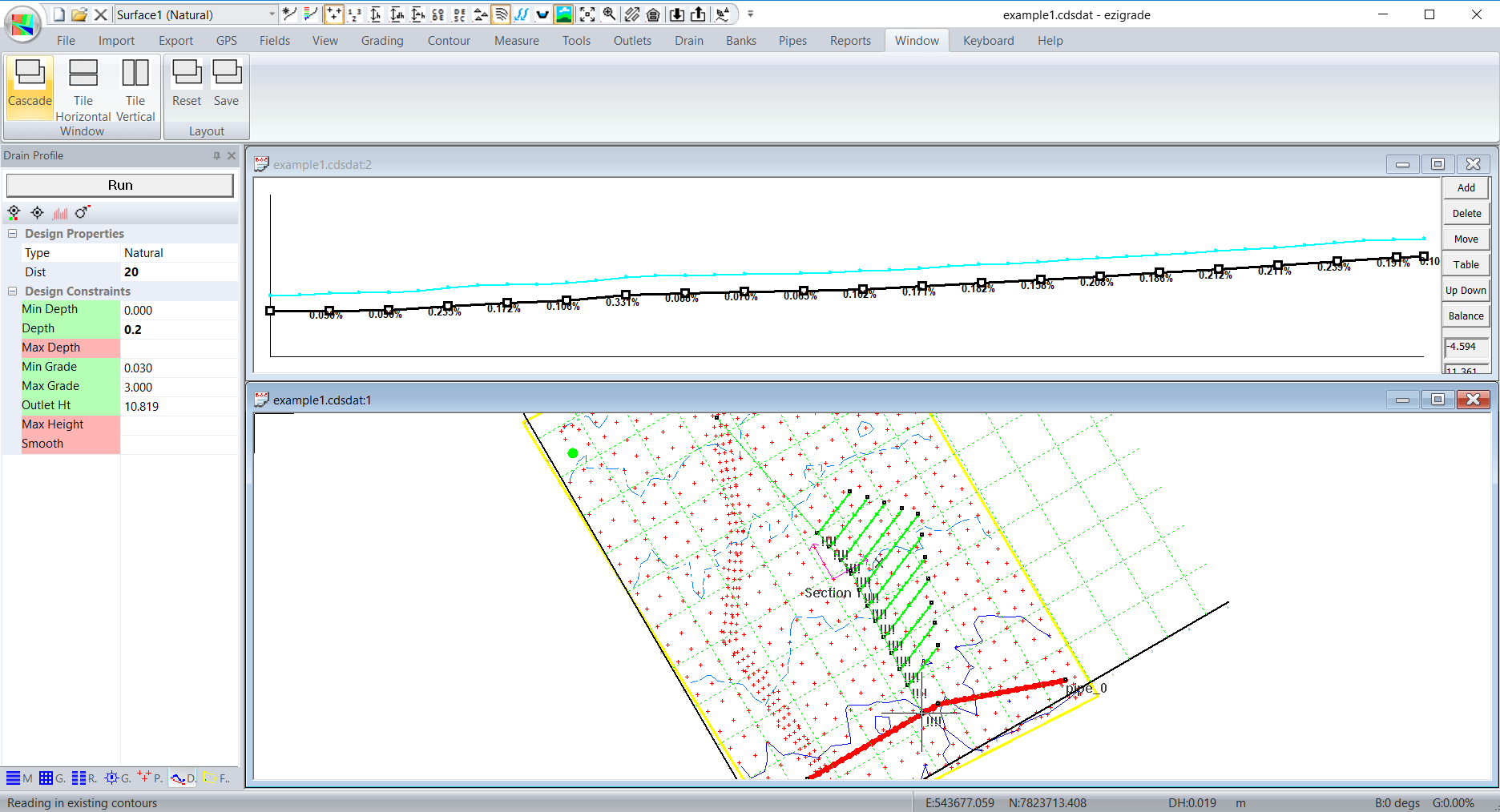
Select a pipe and click on this menu item. We have a profile displayed. If you look left you can also see that the pipe design parameter docking window is also shown (this is same window as the drain docking window). For this screeshot I also clicked on the Window -> Tile Horizontal to get the screen layout shown. We will have a screen similar to below:
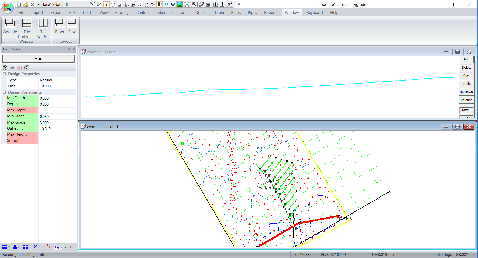
There is no design presently shown as it hasn't been calculated. You can select the parameters on the left and click the run button to create a design to the appropriate constraints. Remember you can also do a design manually if there are specific issues with a pipe. Changing some of the parameters and clicking run and we get this:
You can repeat this for each pipe in the network. However you need to design in order. ie Main first, then Submain and Lateral. This way Ezigrade can set the appropriate "Outlet Height" as we go.
Recalculate All
This goes through and designs all the pipes in order. So for example if you changed the Main design then clicking this will do the design for all the other pipes.
CSV Report
This lists the appropriate lengths of all the mains, submains and laterals as a CSV. You can then easily calculate your pipe costs etc.
There are also a couple of additional menu items under the Export menu. We have presently supported ESRI shape and Trimble XML output formats. For more details please look under the Export menu documentation. Please let us know if you want any additional formats supported.
|