| < Previous page | Next page > |
Rice Paddy design with edge Drains
This still needs to be updated for version4. The drain designs can now be done completely within Ezigrade. Much simpler than the CDS version shown below.
This tutorial shows how we can design a rice paddy using the "Griffith" design methodology. Griffith is a city/town based in Australia which grows rice. Many of the farms are designed in the same way. Please note that the following contains units in both meters and feet. The reason is that the design is based on the Griffith model; which we have taken to use in a design in California near San Diego.
I suggest that you read the previous tutorials first. Some concepts in this tutorial are not explained in as much detail as previous tutorials.
If you are having issues following our design methodology on your job; then please send us your data with what you are after and we will help.
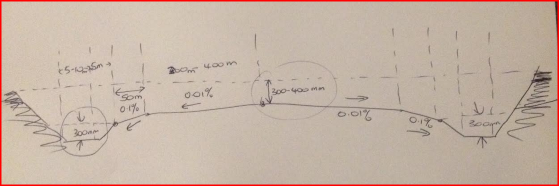
In Griffith they layout there paddy fields down the slope. Each bay has a minimum depth between bays of 175mm. Across the bay there is a crown in the middle. From the middle we slope down at 0.01% for between 300 to 400 meters. For the remaining 50 meters we slope down at 0.1% to a drain that runs down the edge. We slope down into the drain to a depth of approximately 300mm. On the far edge of the drain we slope up so that the far edge of the drain is approximately 300 mm above the crown point of the bay.
A rough sketch of the bay cross section is shown below. (Thanks to Roger Toomey)
In this example we design the actual bay's separately to the drains. The bays are created in Ezicad. We then swing into CDS to create the design for the drains. Each design stage works on its own bit of the natural surface.
Designing the Bays:
We have the following natural surface. This is a field situated near San Diego. It is approximately 60 feet below sea level.
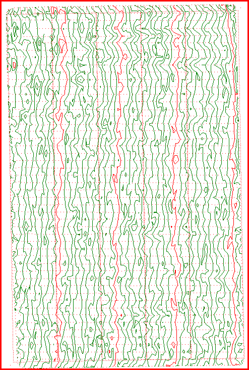
The field slopes down to the left. In this case we wish to design bays that run up and down the page. We will design 5 bays across the page. This is decided by experience. The more the ground slopes the thinner we make the bays.
Ezigrade contains a routine that allows you to layout the bays. For this design we are going to design a bay using 4 sections. The middle section grades at 0.01% and the edge section grades at 0.1%. Where the sections join we need the sections to hinge. This makes the water flow as we desire.
Before laying out the sections we need to set the position of the grid. The layout routine uses the position of the grid when laying out.
Once we have the grid situated at the correct position with appropriate rotation we can use the layout routine. To access the routine use the "Fields" - "Insert Parallel Sections (Bays)" routine. Clicking on this brings up the following dialog box:
 Creating the Sections
I have filled in the values needed for this job. I will now explain what all the values relate to.
Make sure you tick the "delete existing sections". If you are adding in new sections then leave this unticked.
After clicking the OK button the appropriate sections are created. At this stage I suggest that you look at the sections created and make sure every thing looks OK. If not rerun the routine until it all works.
Set the Section Parameters
This bit is a bit of a pain but you need to let Ezigrade know what the grade parameters are for each section. Each section has had the bearing set to the grade of the grid which is what we want. For each section make sure we have the "plane" solution set. For the left edge section set the two x grades to 0.1%. For the y values set them both to 0.0%. If the y values are not set you would get a grade of best fit along the yaxis. Once we have set the approprate grades I suggest that you run the grading. if from the "Grading" menu you can run either the grid or triangle based grading. Have a quick check of the solution. The design is not what we are after as there will be mismatched heights across the bay where the sections meet.
Set the Hinge Lines
A hinge is a concept borrowed from Multiplane. The hinge is a join between joining sections so that the heights meet. The grades of the two sections will change along this hinge line. To set the hinges you simply select each section line. You do this by left clicking on the appropriate line. Once selected they turn green. Once you have selected all the appropriate links then click on the "Fields" - "Toggle Hinge Link". The line swill turn Grey. You may need to hit the escape key. Once you have set these then rerun the grading. The bays should now join. To check this bring up the design contour surface and create some contours.
You may notice that there may be some "bleeding" between adjacent rows. This is because the triangles break across the rows. To clean this up there is a routine in Ezigrade that allows you to add in extra points along the joining links. To do this select all the links between rows. Now from the "Fields" menu there is a routine to "Add points along selected Strings". Once you run this recreate the appropriate triangle surfaces and rerun the grading routine again.
If everything has come together then you should have the following:
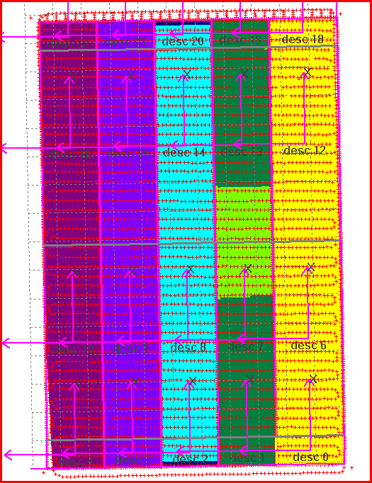
This is the design of the bays completed.
Drain Design:
You will notice that the bay design doesn't extend to the edge of the field. This is done on purpose. We intend to design side drains here. When designing the drains we will create a string that defines the center of the drain. If we look at the top drain - we are designing from right to left - ie down the slope. You may prefer to design the other way; it is your call.
We suggest if you are a novice in CDS road/drain design that you study some of the examples in the CDS manual. In particular look at the dam wall design.
The drain design is as follows:
(1) Click in a couple of points to define the start and end point of the center string. I did this by eye so it was in the middle of the unused section. You may however calculate the points by using any of the generic functions that CDS contains.
(2) Create a string joining the two points.
(3) Select this string. Make sure you are displaying the natural surface and run the "Contour" - "Interpolate profiles and Sections". This gives us some data so that we can design the drain. Once this is done we would display the following on screen. This screen shot also contains the design - whose explanation follows.
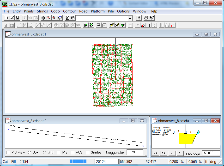
(4) Display the profile and section view. Do this by clicking on appropriate icons.
(5) Design the profile line. The bottom of the drain lies approximately 300 ml below the edge of the field. To ascertain the heights I would suggest you switch to design surface and manually read off the heights at the edge of the job. You can then ascertain the height by dropping it 300mm (1 foot in this job). To click in the design heights right click in the profile view and select the add option. You can then enter point at start and end of job. You can fine tune these points by moving them or alternatively editing them in the "design IP table". Both these functions are brought up from right mouse button.
(6) We now can design the section templates to achieve what we need. To the left of the drain centre line we want a left edge of the bottom of the drain channel. We will simply let this join up to the existing bay design so we need do nothing else here. On the right we wish to go to edge of the channel and then grade up to a point a fixed offset and a height that is designed. The right hand side template is seen below:
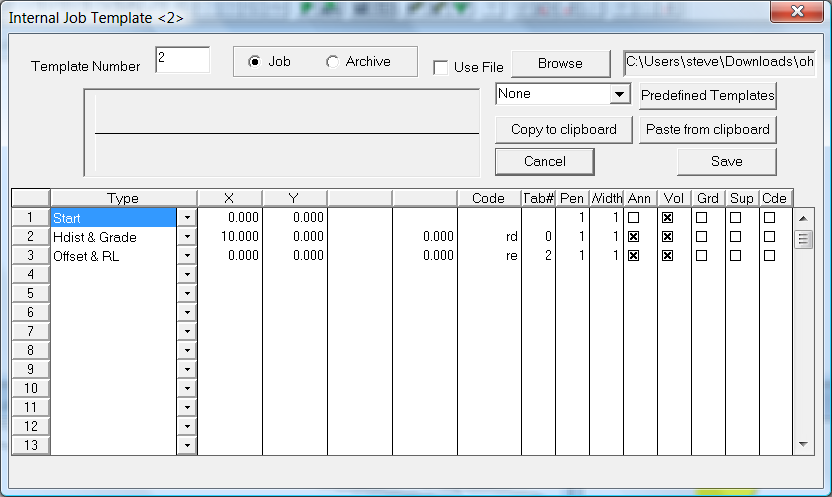
The first line is simply the start point. The second line draws right edge of the channel at 10'. (so total width is 20'). We then draw to a fixed offset and RL. In this case we get the appropriate heights from Variable Table 2.
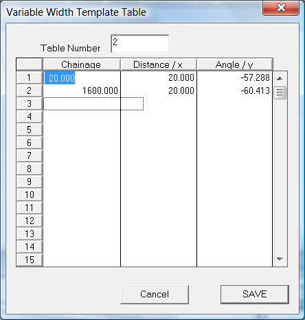
So at start we have a height of -57.288 and at end we have -60.413. These values are calculated from the center of the bay. We get the center height and add 1'. A previous screen shot shows how it looks like in section view.
Once you are happy with the design it is time to incorporate these design points into the job. Under the "Road" menu there is an option to "Store Design Heights". The dialog is seen below:
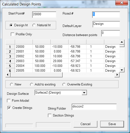
It is suggested that you start the points at a new point range. This makes it easier to delete them etc if something goes wrong. We are also creating strings along edges of the design and placing them in the discon2 folder. This creates breaklines for us for nicer triangles.
(7) Create new design surface with these new points. Under contour - surfaces; you may need to tweak the point range etc
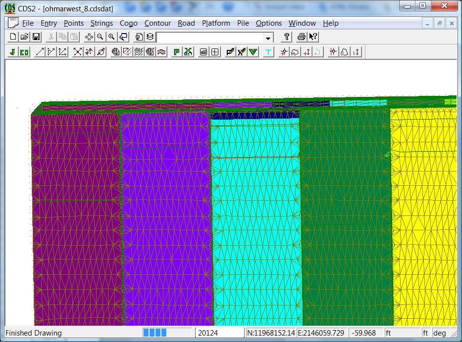
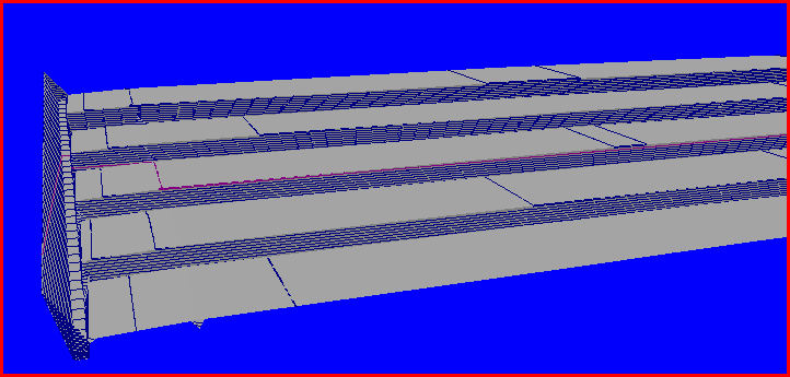
(8) Surface now looks like this:
and for a 3D View: The view below has a vertical exxageration of 100:1.
We have now designed the right hand drain.
You would design the left hand drain the same way.
Balancing Cut/Fill:
Ezigrade automatically balances the cut and fill for us taking into account the compaction factor.
When doing the drain design the road-works routines also have volume calculations. If you can balance them here then nothing else needs to be done. If the drain earthworks don't balance then you can balance the whole job in CDS. Use the "Volumes between 2 Surfaces" routine over the whole job. If there is an imbalance you can coorect in Ezigrade by exporting or importing dirt to a section/sections and redo the grading. You would then check again to be sure.
|