| < Previous page | Next page > |
Design within CDS
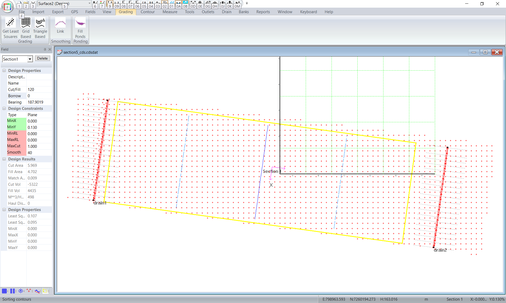
In this method we use the road design package within CDS to create the design in one contiguous structure. This has the advantage that we are only doing the one design so it is probably easier to balance volumes etc.
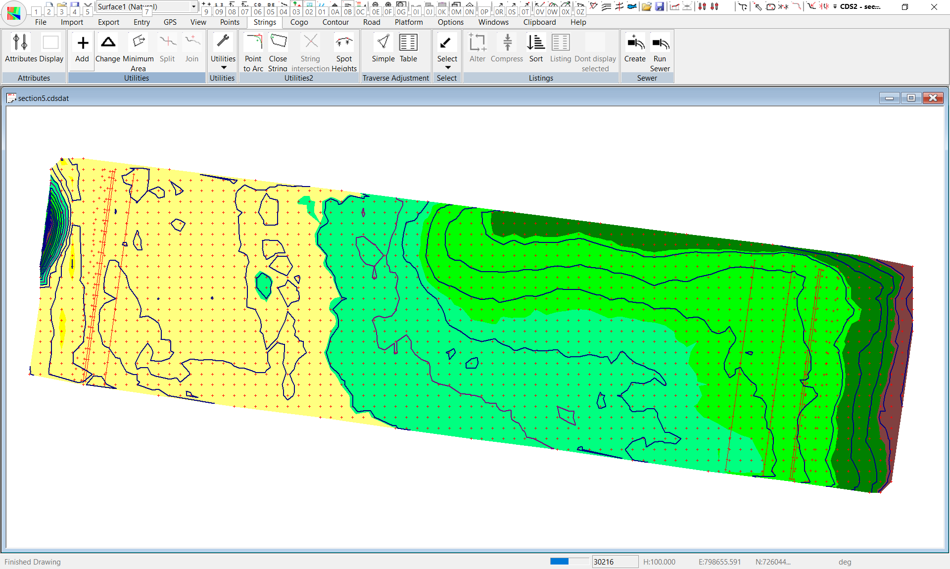
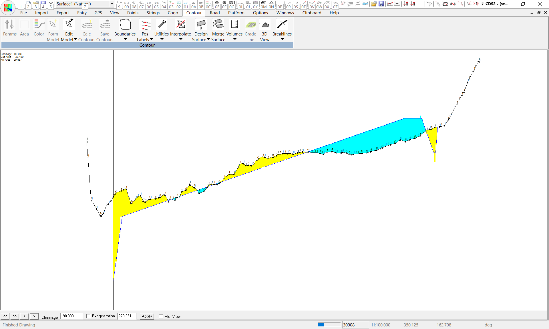
If you look at the screen shot above we have a number of strings. We are going to use the right edge of the table drain, the left edge of the section, the right edge of the section and the left edge of the head ditch.
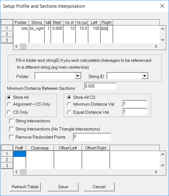
In CDS left click on the table drain string and then run Contour -> Interpolate -> Profiles and Sections. Set the sections to be 10 meters apart and look 100 meters to the left and 800 meters to the right. As long as it covers the design area. Click "OK + Save" to store away the data.
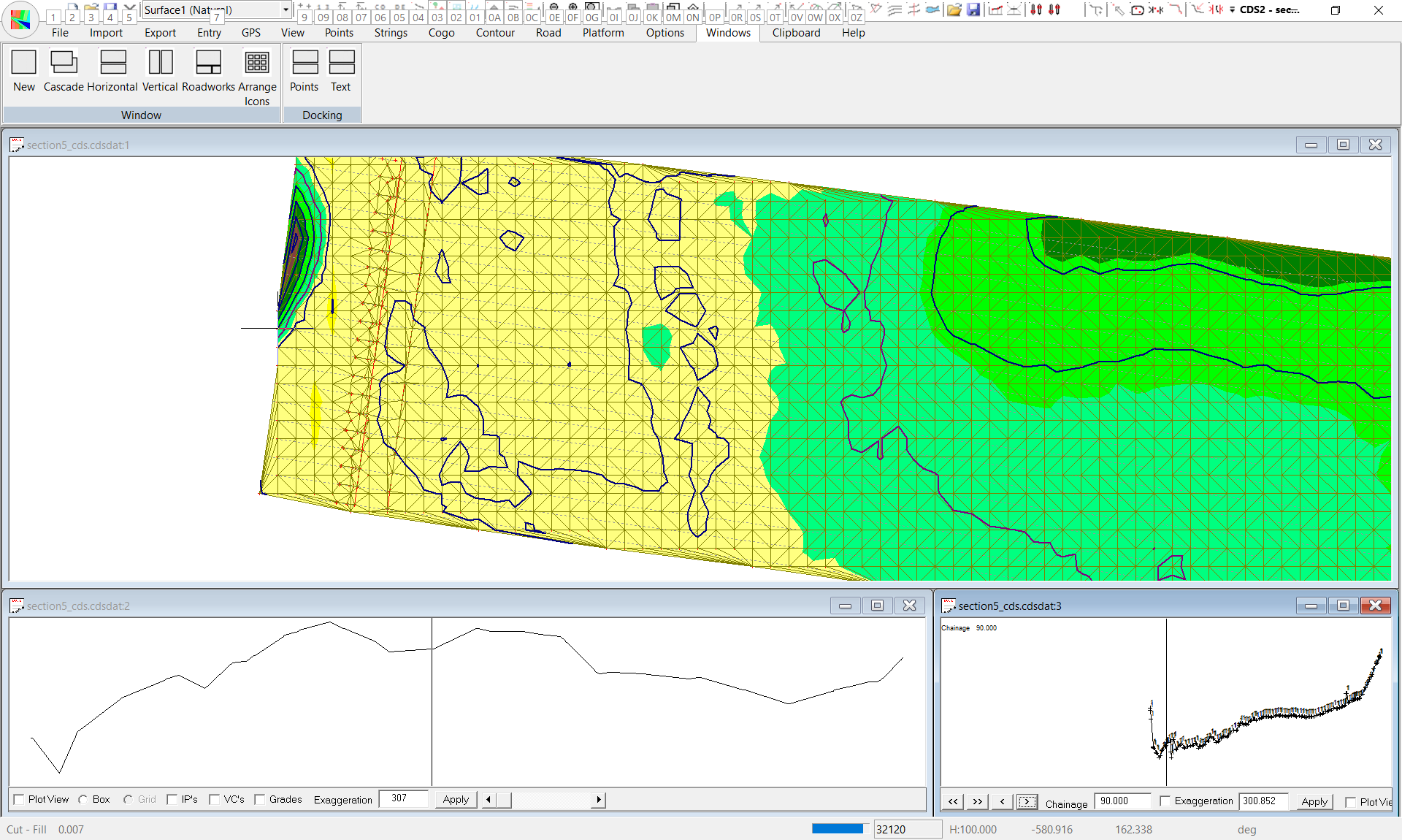
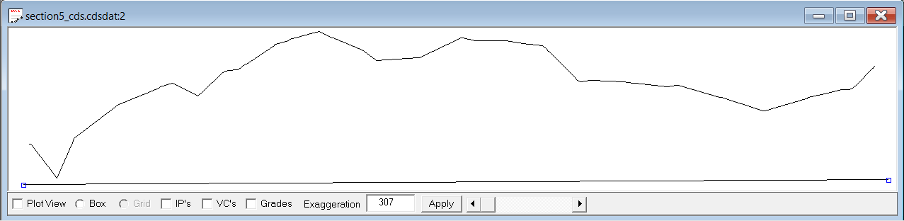
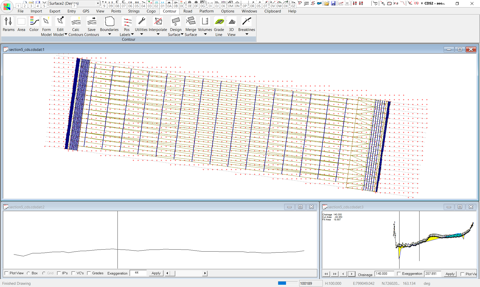
This has created sections. Click on Road -> Display -> Display/Print -> Display Profile and Display Section. Now click on Windows -> Road Works and we have the following.
Move through the sections to confirm things look OK. We are going to put a profile design along this section and create a template that creates our structure. We need to create the profile design along this profile. Left click into the profile view and right click and hit menu item to add. Click in two points before and after the data as below:
Now right click again and select IP table: Change the heights to 162.136

Click on Save. We will design the section later.
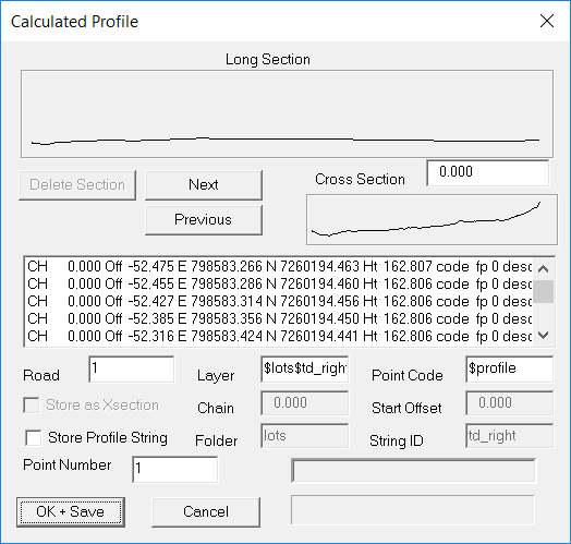
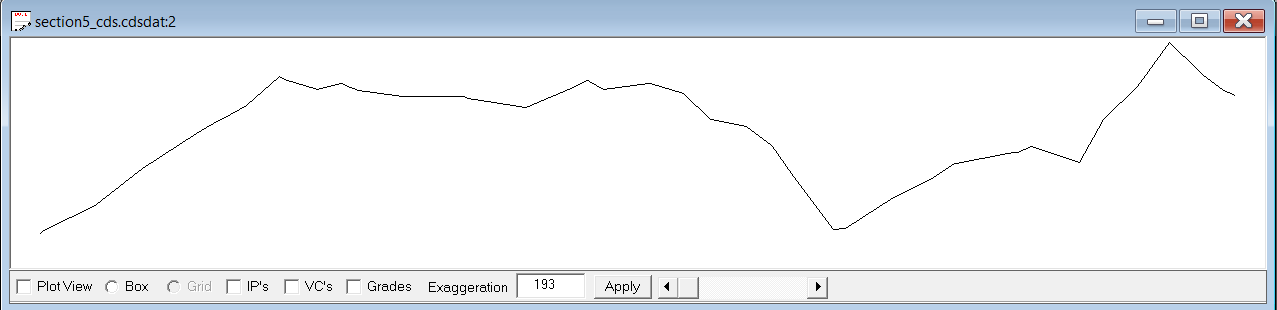
Now click on the left edge string and click on Contour -> Interpolate -> String Profile. We only need a profile here. We already have a section over the whole job.
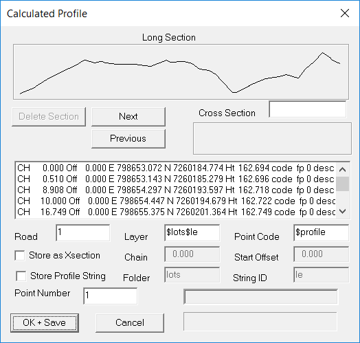
Click OK and Save and this new profile is now in the profile view. You may need to type ze (zoom extents) for it to fill the screen as below:
Now we need to specify a profile design as before. However at this time we are not exactly sure what value we should be using here. We can use Ezigrade here to give us a hint. Close down CDS and open in Ezigrade.
Roughly click in a section and run the grading: Move your mouse to left edge of the section and then right edge and note the heights. They are 162.625 and 163.372 respectively. Use these as a guide.
Open the job back up in CDS: show the profile view and display the design IP table and enter in the values of 162.625 as below:
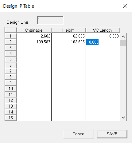
Repeat for the right edge profile and use a height of 163.372
Now do the left edge of the head ditch and we are use a design height of 163.113
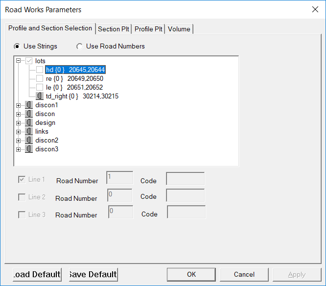
We are now in a position to create our section for the whole structure. Click on Road -> design criteria -> profile parameters. Change the selection to the td string:
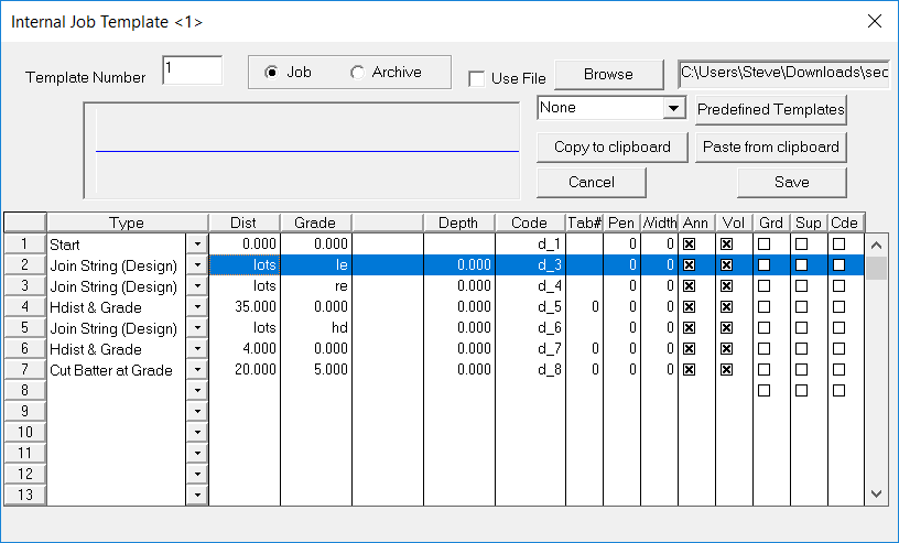
Click into the section view and then right click and select standard templates. Here we have entered a template 1. Lookint at the template. We are going to hang this of the right hand side of the tail drain. We are going to join straight to the left edge of the section. This is the lots le string. Use a type of Join String (Design). It looks up the le string profile. Repeat going tp the re string. Draw in the sill and as a shortcut lets join straight to the left edge of the head ditch. Now draw agross the base of the head ditch and batter up to the natural surface.
Right click into the section view again and set the template usage table. Set to use 1 for each section. Click through each of the sections to make sure it looks right by inspection.
We need to flesh out the drop into the head ditch and also put in the batter from the table drain. We are going to create a template 2 that draws in the bottom of the tail drain with a batter. Template 2 is below:
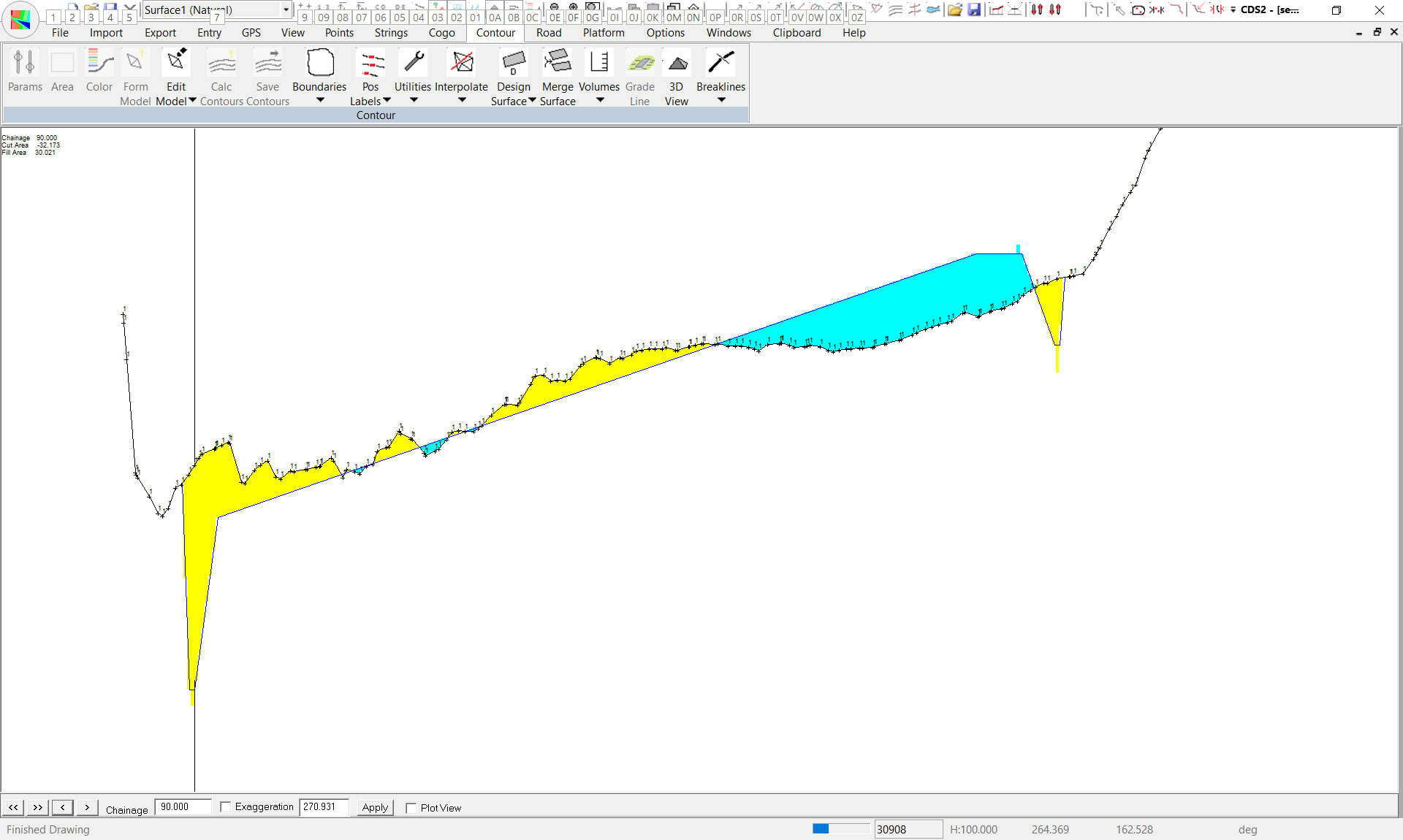
We are now in a position to calculate some volumes. Running volumes Road -> Volumes -> Design Volumes we get volumes of -8539 / 5985. With a difference of 5985 - 8539/1.2 = -1130. So we have too much cut. To compensate we need to raise the area of the section plus the sill. Under Cogo -> Surround. Click in the area to get the area we are looking at. It is 120,900 meters squared. Thus try raising the area 1130/120900 = 0.009 meters.
We go into the left edge profile and change the design and also the right edge profile by 0.009.
Recheck the sections and run the volumes again.
We get -7970 and 6543 which is a difference of about 100 m**3. Good enough.
At this stage you would go in and flesh out the template around the head ditch and recheck the volumes.
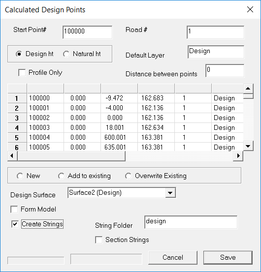
We can now add in our design points:
Go to Road -> Design Surface -> Store Design Points. I changed the start point number to something we can remember. If we want to delete what we have done and start again. Also click on create strings. Clicl "Save"
.
Once saved create a design surface, form triangles and contours and check what we have.
At this stage you may need to go into Ezigrade to export this to your controller of choice.
|