| < Previous page | Next page > |
Fields Menu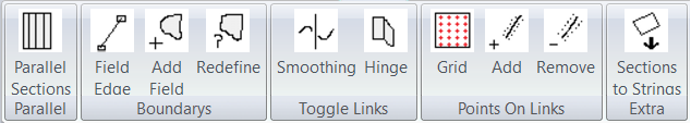 What is a Field / Section:
There is no need to define a section if you wish to grade the whole field using the same parameters. If you wish to define only a certain section of the job then you can create a section. It is simply a closed area. It has a number of defined lines that make up the outside of the field. The field has a number of parameters associated with it such as cut/fill ratio etc.
By having two or more sections you can set different grades in different sections.
There are options to create either a hard interface between the two sections or a smooth section between sections.
The fields menu has the following options:
Insert Parallel Sections:
This function automates the entry of parallel bays. For example if designing rice bays or similar.
Clicking on this option brings up the following dialog:
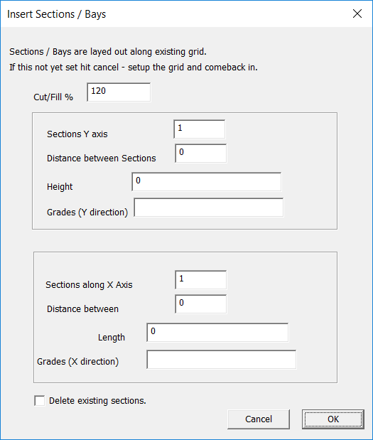
You are prompted to enter Number of sections, Length and Height. You can also delete all existing sections or add to existing. The sections are designed to use the existing defined grid. It takes the origin and lays out the length along the X axis. The sections are added in along the Y axis.
If you need to enter a number of different parallel bays then enter the first series of sections. Then move and rotate the grid as appropriate. Now enter the second set of parallel bays. Repeat as needed.
Insert a Field Edge:
This option allows you to click in a series of lines. Once you have run the menu item the procedure is:
Please be aware that you can automatially snap to existing line end points or to a point along a line.
Add Field:
Before running this option you first need to select a series of existing field edges. They need to form a boundary, ie close. After you have run this option a new field/section is formed and you will need to add in appropriate parameters.
Redefine Section Boundaries:
Before running again select existing edge points that make up a closed boundary. Running this option fixes up a field that is either in error or needs to be changed.
Store Fields as Strings:
This option takes the defined sections and creates a series of closed lots within the database. If you know open the job in CDS you can work on these strings as any other defined strings. Common uses are creating print-outs, areas and exporting plots to a dxf/dwg file.
Toggle Common Links:
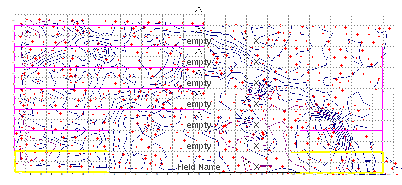
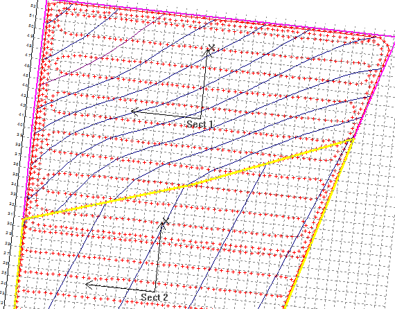
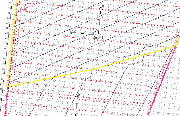
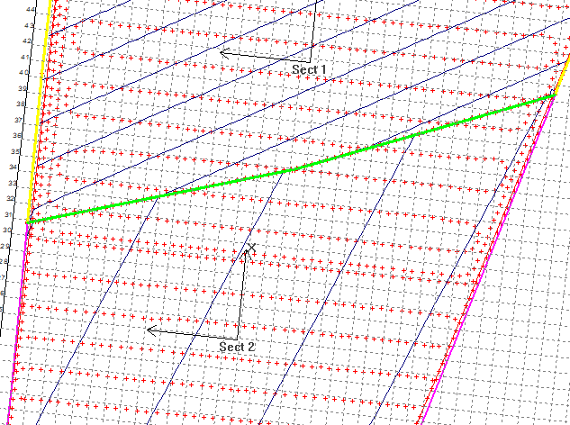
What is a common link. Ezigrade lets you define edges that join sections as common links. When it is common it means that when smoothing is run the smoothing is carried out across the common link. If it is not a common link then the grading is performed on each side of the link but points across the link are not used.
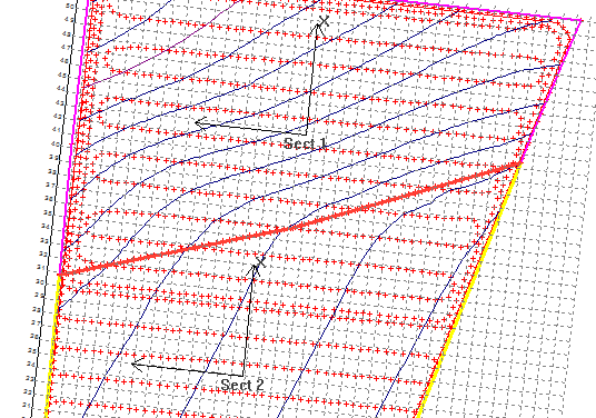
The two examples below show the difference. The first example smooths both sections and gives a soft interface. The second example gives a hard interface. With the plane the smoothing will have no effect as a plane is already smooth. In the first example the points near the common edge are affected due to the influence of the neighbouring section.
  Grid
This option strips out the existing points used within a section and replaces them with points in a rectangular grid lying along the section axes. Please click the link for a detailed description.
Add Points Along Selected Links:
I guess the first question is why should I be doing this. This function adds in additional points both sides of an existing link at an offset. The default is 0.5 meter. This is particularly useful when you have a number of plane sections close to each other. The finished surface uses the existing points and triangles. It can lead to a jagged line effect. When we add in extra points the plane has a crisp edge.
Look at the two screen shots below.
When you run this routine you are presented you are asked for an offset and distance between points and new point number. The offset is the distance from the link and the distance is the difference along the link. Adjust these values depending upon your job.
After running this you will need to recreate the natural surface DTM. Also once you have graded the job you will need to recreate the design surface DTM otherwise these points will be ignored in the final output.
Delete Points along selected links:
Select the appropriate links and hit this menu item. Additional points will be removed. You will still need to reform any natural, design triangles etc.
Sections To Strings:The contents of Fields Menu |